
Coil Packing Line Installation & Site Preparation: A Pre-Contract Buyer's Guide (2026)
Research report for PC Package · Published October 2026 · Prepared by an independent technical team. Companion piece to the Steel Coil Packing Line: Manufacturer Comparison & Buying Guide (2026), the Turnkey vs Component Sourcing: Procurement Risk Guide (2026), and the EU CE Compliance & Safety Verification Buyer's Guide (2026).
Executive Summary
Site preparation is the part of a coil packing line project that is quietly expensive to get wrong. The machine price, the supplier comparison, and the CE documentation strategy all get attention during procurement; the floor, the electrical supply, the air line and the lifting plan — the engineering services that connect the line to your building — are often assumed away until installation week, when they become critical-path and expensive to fix.
Bottom line: before you sign, confirm — in writing, from the supplier's layout drawing (GA) and foundation requirements — six site facts: (1) line footprint, (2) floor/foundation requirement, (3) electrical supply (voltage/frequency/load), (4) compressed-air supply, (5) lifting/crane plan, and (6) MES/ERP interface scope. Getting these six agreed at quotation stage converts a risky "install when it arrives" surprise into a planned, scheduled activity — typically the difference between a scheduled 6–10 day installation+commissioning and an open-ended one.[1][2]
Three site facts nearly every buyer should expect from a standard automatic coil packing line:
- Floor & foundation: most equipment runs on ordinary cast concrete industrial floor with no special foundation; heavier stations (balancers, stackers, down-enders) may need a defined plinth or pit per the foundation drawing.[1]
- Electrical cabinets: a small single line ships a cabinet about 0.8 m wide; mid-size lines 1.2–1.6 m; the largest lines up to 3.6 m cabinet width — this matters for access aisles, crane door openings and control-room placement.[1]
- Air supply: stations with pneumatic cylinders (down-ender, film cut-off, guard interlocks) need dry compressed air supplied to each valve manifold, typically around 6 bar, delivered at the battery limit.[2]
The report provides: a station-by-station site checklist (§3), the FAT→shipment→installation→SAT→acceptance timeline with real durations (§4), the six-field site-readiness table you can attach to your RFQ (§6), and a pre-shipping site-readiness sign-off (§7).
Site requirements vary by line configuration and supplier; figures below are indicative and negotiated against the supplier's GA and foundation drawings for your specific line.[3]
1. Why Site Preparation Is a Procurement Task, Not an Installation Task
For a coil packing line, the physical site connects every decision made in the other three companion guides:
- From the comparison guide: the line you choose defines the footprint you must make room for.[4]
- From the procurement-risk guide: battery limits between stations are where ownership of interfaces (pneumatic drops, electrical terminals, control handshakes) is contractually assigned.[5]
- From the CE guide: installation is when the line becomes the "assembly of machinery" whose line-level DoC you and the integrator sign off at SAT.[6] Note the transition underway in EU regulation — Directive 2006/42/EC remains valid until 19 January 2027, after which Regulation (EU) 2023/1230 applies; a line commissioned around that boundary should confirm its legal basis with the integrator at contract stage (see §4 of the CE guide).[6][7]
Site work is therefore not "someone else's job on site in week 8". It sets the schedule, the cost, and the acceptance criteria weeks before the equipment ships.
The typical failure pattern: a buyer signs for the machine, then discovers at the pre-shipment visit that (a) the electrical cabinet needs a wider crane door than planned, (b) the plant air cannot deliver dry air at the required flow where the wrapper stands, or (c) the MES/ERP interface was never scoped so the weighing/labelling station cannot talk to the plant system. Each of these is a weeks-long delay and a change-order once the line is committed. Each is preventable at RFQ stage.[1][2][3]
The discipline this guide adds: treat site preparation as a specification deliverable, not an afterthought. The supplier's layout/GA drawing and foundation requirements should be part of your signed scope, dated and aligned to your actual building (column positions, doors, crane coverage, existing services' locations).
2. The Eight Site Systems to Plan (Overview)
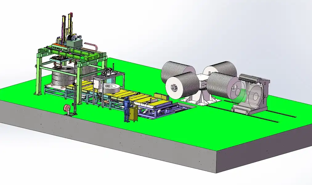
Eight building systems interact with the line. Seven are physical or electrical; the eighth is data. Confirm each against the GA drawing before signing:
| # | Site system | What it connects | Will it likely require work? |
|---|---|---|---|
| 1 | Floor & foundation | Every station's weight-bearing and plinths | Most: cast concrete floor OK; heavier stations per foundation drawing[1] |
| 2 | Electrical supply | Feed, cabinet, station motors/drives | Yes: dedicated feed and suitable isolation/disconnect usually needed[1] |
| 3 | Compressed air | Pneumatic cylinders at down-ender, film cutoff, interlocks | Usually: dry air to valve manifolds at battery limit (~6 bar)[2] |
| 4 | Lifting / crane plan | Installation of heavy stations, and cabinet placement | Yes: lifting equipment is the buyer's responsibility during installation[1] |
| 5 | Access & aisle space | Cabinet access (0.8–3.6 m), maintenance aisles, coil traffic lanes | Usually: layout planning needed[1] |
| 6 | Network / control interface | PLC-to-PLC, and upstream/downstream equipment handshakes | Depends: control handshake scope per battery limit[2][5] |
| 7 | MES / ERP / labelling data | Weighing, labelling, production data | Often excluded from "machine" scope — confirm separately[1] |
| 8 | Safety & guarding space | Fencing, light curtains, E-stop zones, escape routes | Yes: guard layout is part of the line design[2][6] |
3. Floor & Foundation: What the Standard Line Needs
The most common misconception is that a coil packing line needs expensive special foundations. In practice, for a standard automatic line:
- Most stations run directly on ordinary cast concrete industrial floor with acceptable flatness; no special foundation is required for standard machines.[1]
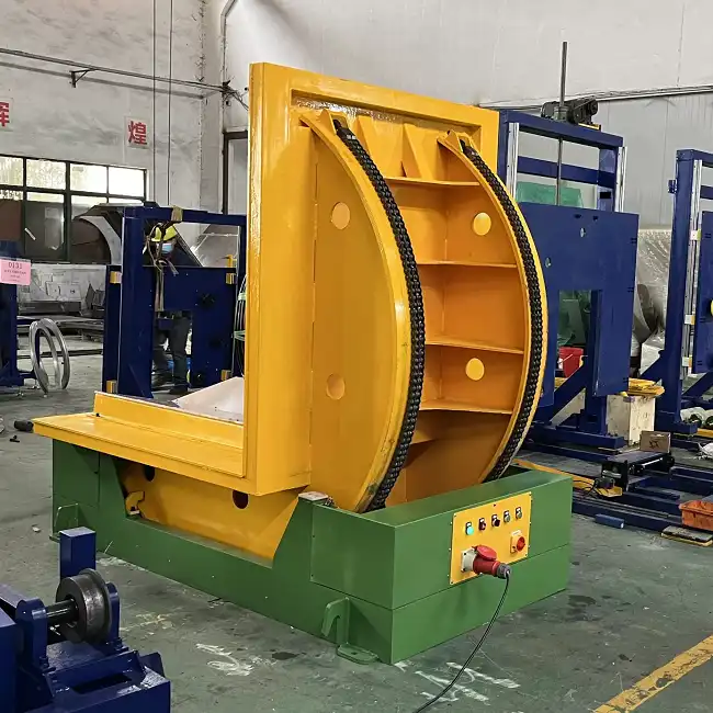
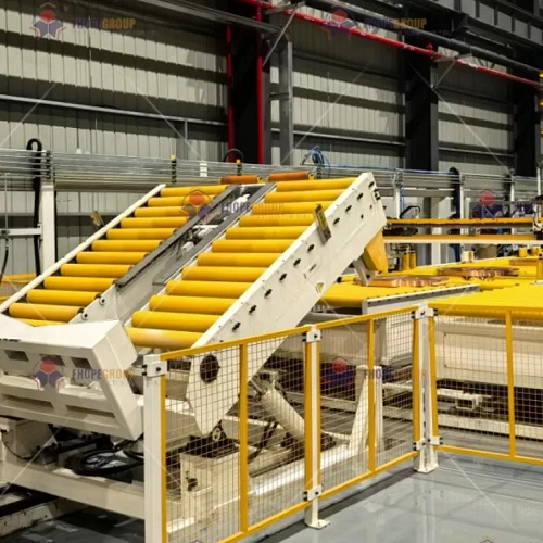
- Heavier stations — such as a down-ender handling full 5 t+ coils, a coil balancer, or a stacker — may need a defined plinth or pit; the supplier provides the foundation drawing and requirements with the design.[1]
- Stacking of 4–5 t coils is done by forklift-arm or electromagnetic stackers, whose floor embeds and footprint should be verified against the foundation drawing.[1]
What to request at RFQ: the supplier's foundation requirements (flatness tolerance, pit/plinth details, anchor positions) with the quotation, and a foundation drawing with the design. If the line is a retrofit into an existing mill, verify the existing slab and any drainage/vibration constraints are captured in the site survey you hand to the supplier.[1][3]
Dynamic-load nuance (why the foundation drawing matters, not just the floor): a standard roller conveyor and a wrapper ring are statically loaded and typically run on an ordinary slab. A down-ender / tilter and a stacker are different: tilting a full coil applies a dynamic, concentrated load during the 90° move, so those stations commonly need a thicker or separately designed base with proper anchoring, per the supplier's foundation drawing. Do not assume "concrete floor is enough" — ask the supplier to state, station by station, which ones sit on plain floor and which need a plinth/pit or heavier base with anchors. This is a quotation-stage question, not an installation-week discovery.[1][3]
4. Electrical & Compressed-Air Supply at the Battery Limit
Two services dominate installation planning:
Electrical supply.
- Voltage/frequency/phase: confirm the line's rating matches your plant (a common export baseline is 380–415 V, 3-phase, 50 Hz, though the exact figure is per configuration — the FPL-2500 line reviewed in the companion comparison guide is rated 380–415 V, 3-phase, ~25–40 kW).[4]
- Cabinet sizes: a small single machine ships a cabinet ~0.8 m wide; mid-size lines 1.2–1.6 m; the largest lines transport cabinets up to 3.6 m wide.[1] Plan the approach path, crane-door width, and control-room location around the actual cabinet footprint.
- Feed & isolation: a dedicated feed with suitable disconnect at the line is normal; confirm scope split (who supplies the cable, who terminates) in the battery-limit schedule.[2][5]
Compressed air.
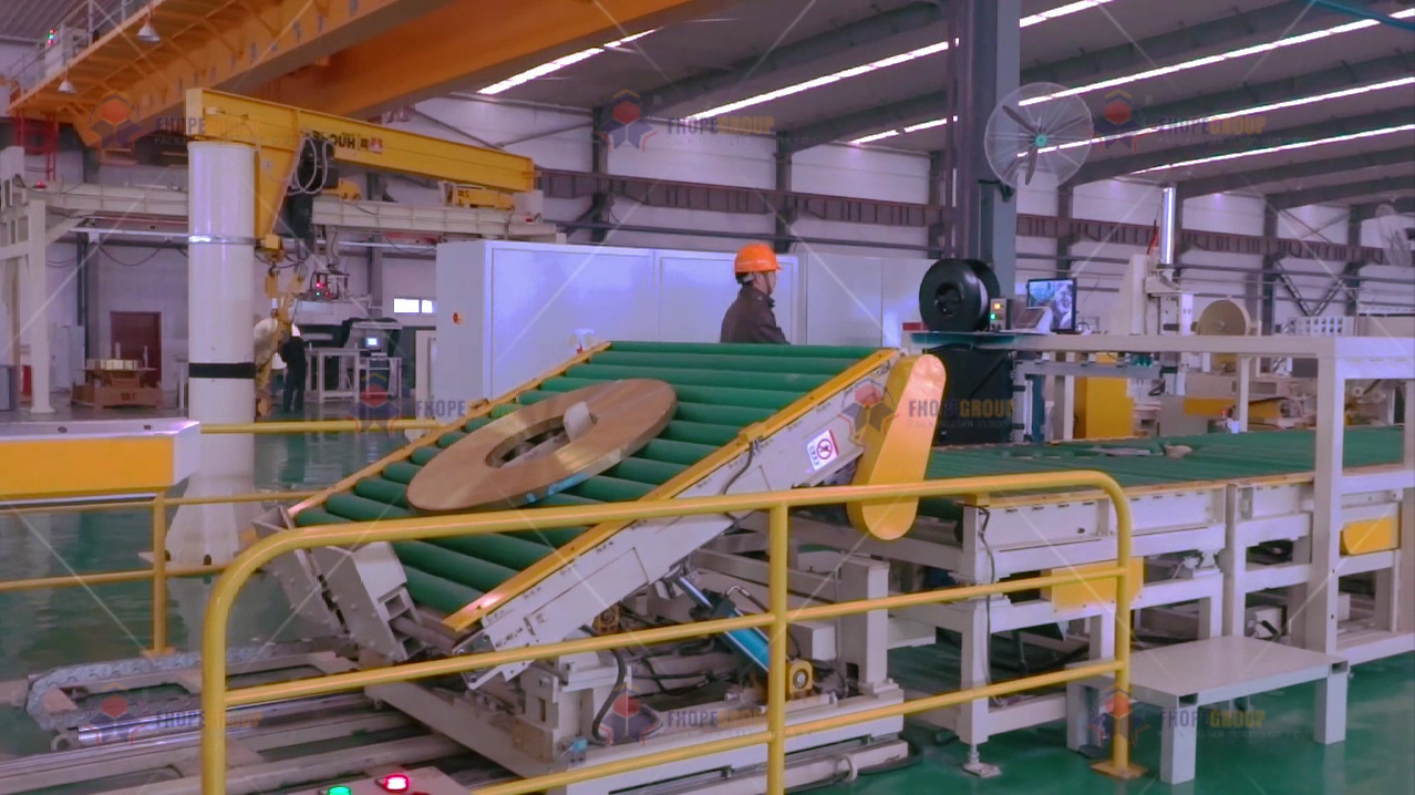
- Stations with pneumatic cylinders — down-ender, film cut-off, interlocked guards — need dry compressed air supplied to each valve manifold, typically around 6 bar, delivered at the battery limit.[2]
- Confirm (a) flow/consumption figure, (b) dryness requirement — ask the supplier to state the required air-quality class (for reference, ISO 8573-1 classifies solid/water/oil content) rather than accepting a vague "dry air", and (c) who installs the final drops and regulators — at quotation, not at installation.[2][3]
Interface with the electrical safety scope: the power isolation and the E-stop chain are part of the same battery-limit/control-handshake conversation covered in the CE guide — EN 60204-1 supply disconnection and EN ISO 13849-1 safety logic across stations.[6][8]
5. Lifting, Access & Layout: Installation-Week Reality
Lifting is the buyer's responsibility. During installation, the lifting equipment (crane, forklift, rigging) is provided by the buyer.[1] Confirm the weight of each shipping unit (typically each station ships separately; heaviest items are the wrapper ring, the down-ender and, where fitted, the stacker), the crane capacity/door clearance needed, and the access route before week 8.
Access aisles and cabinet placement.
- Cabinets up to ~3.6 m wide on the largest lines change the plant layout: aisle width, door opening, and panel-room placement must clear the actual cabinet footprint.[1]
- Maintenance access around the wrapper ring and the strapping/wrapping interface should be in the GA — verify walkways and guard positions meet your maintenance practice.[2][6]
Layout integration with upstream/downstream.
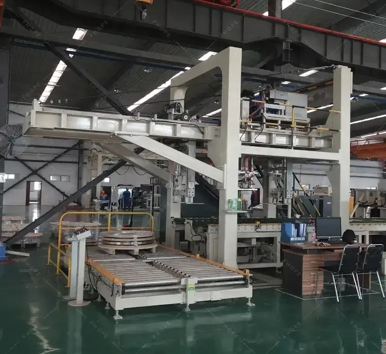
- The line's in-feed ties to your existing conveyor/slitting exit; the out-feed to crane aisle or truck bay. Confirm coil traffic lanes width for your coil sizes (coil widths and OD per your product mix) and the transfer heights align.[3][4]
6. The Pre-Contract Site-Readiness Table (Attach to Your RFQ)
Copy this into your RFQ/contract annex. Six fields, each confirmed in writing before you sign:
| # | Site readiness item | What to confirm | By whom |
|---|---|---|---|
| 1 | Line footprint (GA drawing) | Overall length/width, station positions, and alignment to your building columns/doors | Supplier provides GA; buyer verifies against building |
| 2 | Floor & foundation | Flatness tolerance, plinths/pits, anchor positions; existing slab adequacy | Supplier provides foundation drawing; buyer confirms building |
| 3 | Electrical supply | Voltage/frequency/phase/load; feed responsibility split; cabinet footprint (0.8–3.6 m) and access path | Both: supplier states ratings; buyer provides feed |
| 4 | Compressed air | Pressure (~6 bar), flow/dryness, valve-manifold drops at battery limit; who installs final drops | Supplier states demand; buyer provides dry air line |
| 5 | Lifting plan | Ship-unit weights, crane capacity/door clearance, buyer-supplied lifting equipment, access route | Buyer owns lifting; supplier states unit weights |
| 6 | MES/ERP & labelling data | Weighing-ticket fields, labelling content, MES/ERP protocol & data fields — jointly defined | Both: interface spec confirmed at RFQ[1] |
| 7 | Network/control handshake | PLC-to-PLC status words, upstream/downstream signals at battery limit | Supplier per battery-limit schedule[5] |
| 8 | Safety & guarding space | Fencing, light curtains, E-stop zones, escape routes on GA | Supplier per safety design[6] |
7. The FAT → Shipment → Installation → SAT Timeline
Understanding the real durations prevents two errors: booking installation resources too early, and letting the site sit idle waiting for a line that is still in FAT.
| Phase | Typical duration | Buyer's task |
|---|---|---|
| FAT (factory) | 1–2 days (standard machine); ~1 week (custom); 10–15 days (large custom line); ~30 days (large turnkey project) | Attend or accept video FAT; clear FAT rejection points[1] |
| Shipping | per logistics plan (often 1–3 containers, see comparison guide's logistics note) | Confirm customs/import per HS 8422.40, ensure receiving crew[4] |
| Installation (on-site) | typically 6–10 days for an automatic-line installation+commissioning including site wiring and program connection to existing systems | Buyer provides lifting; station placement; site services live[1] |
| SAT | hot production run of 4–8 continuous hours + training | Sign-off; operation team present[1][5] |
| Training | 1–3 days standard; ~3 days automatic line; optional production-accompaniment package | Ensure operators scheduled[1] |
Schedule planning logic: because installation + commissioning is commonly 6–10 days and SAT adds a 4–8 h hot run plus training, the total on-site window from truck arrival to signed SAT is typically 2–4 weeks controlled by how many engineers the scope includes and how ready the site is. A site that passes the §6 readiness table is the difference between that planned window and an overrun.[1][3]
8. FAQ
Does my steel coil packing line need a special foundation?
No for most stations; verify the heavy ones. Most conveyor, wrapping and strapping sections run on ordinary cast concrete industrial floor with acceptable flatness; heavier stations (down-ender, stacker, balancer) may need a defined plinth, pit or anchored base per the supplier's foundation drawing. Confirm flatness tolerance and any pit/anchor details with the quotation, station by station.[1][3]
Who provides the lifting equipment for installation?
The buyer. During installation, lifting (crane/forklift/rigging) is provided by the customer; the supplier provides the line, engineering and commissioning. Confirm ship-unit weights and crane/door clearances before delivery.[1]
What electrical and air supply does an automatic line need?
Electrical: line rating typically 380–415 V, 3-phase, 50 Hz (per configuration, ~25–40 kW for the reviewed line), with cabinets from ~0.8 m (small single machine) to 3.6 m (largest lines). Compressed air: dry air supplied to each valve manifold at the battery limit, typically ~6 bar. Confirm feed responsibility and flow/dryness at RFQ.[1][4]
What if my plant MES/ERP needs line data?
Weighing data, labelling content, and MES/ERP fields/protocols are jointly defined with the supplier — this is typically outside the "machine" scope and must be confirmed at RFQ, not after commissioning. Ask for the interface specification in writing.[1]
9. References
[1] Confirmed supplier installation & site facts (Yoki, supplier engineering, 2026-10-10): floor/foundation practice for standard lines, electrical cabinet transport widths (0.8 m / 1.2–1.6 m / 3.6 m), lifting during installation supplied by buyer, FAT duration by project size (1–2 days to ~30 days), SAT hot run 4–8 h, training 1–3 days (automatic line ~3 days), retrofit changeover 6–10 days, stacking 4–5 t coils via forklift-arm/electromagnetic stackers, MES/ERP fields jointly defined.
[2] PC Package. "Turnkey vs Component Sourcing for Steel Coil Packing Lines: A Procurement Risk Guide (2026)." https://pcpackage.ch/turnkey-vs-component-sourcing-steel-coil-packing-lines/ — battery-limit schedule (mechanical datum, pneumatic drop, network gateway, control handshake), FAT/SAT acceptance framework.
[3] Site requirements vary by configuration; GA and foundation drawings for the specific line are the authoritative source; indicative figures marked as such.
[4] PC Package. "Steel Coil Packing Line: Manufacturer Comparison & Buying Guide (2026)." https://pcpackage.ch/steel-coil-packing-line-comparison-top-4-manufacturers-2026/ — FPL-2500 rating (380–415 V, 3-phase, ~25–40 kW), line subsystems, logistics, HS 8422.40.
[5] Battery limits and integration ownership as defined in procurement-risk guide; electrical/pneumatic drops and status-word handshakes ownership.
[6] PC Package. "EU CE Compliance & Safety Verification for Steel Coil Packing Lines: A Buyer's Guide (2026)." https://pcpackage.ch/ce-compliance-safety-verification-steel-coil-packing-lines/ — EN 60204-1 supply disconnection, EN ISO 13849-1 safety logic, assembly-of-machinery DoC at SAT.
[7] EUR-Lex. Regulation (EU) 2023/1230 on machinery, replacing Directive 2006/42/EC with effect from 20 January 2027 (Directive 2006/42/EC valid until 19 January 2027). https://eur-lex.europa.eu/eli/reg/2023/1230/oj/eng [Accessed: 2026-10-18]
[8] CEN / ISO / IEC. EN 60204-1 Electrical equipment of machines (supply disconnection, emergency operation) and EN ISO 13849-1 Safety-related parts of control systems (performance levels for safety functions) — harmonised machinery-safety standards also cited in the companion CE guide.
Last updated: 2026-10-18
About this article: This installation & site-preparation guide was prepared for PC Package as independent analysis accompanying the manufacturer-comparison, procurement-risk and CE-verification guides. It describes indicative engineering practice and supplier-confirmed site facts; the supplier's GA and foundation drawings for your specific line are authoritative. Figures are illustrative reference images from the supplier's product library and are for context only.