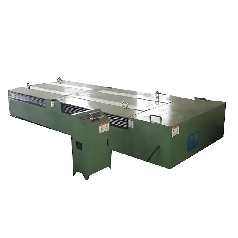
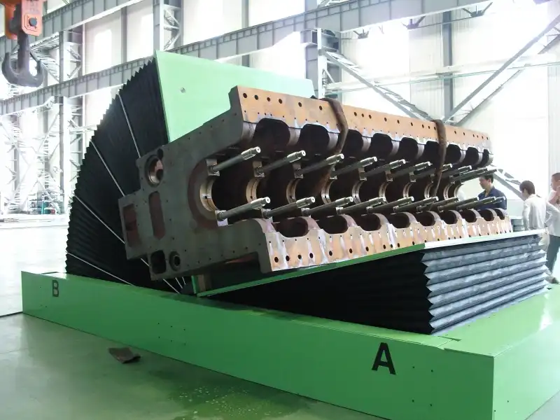
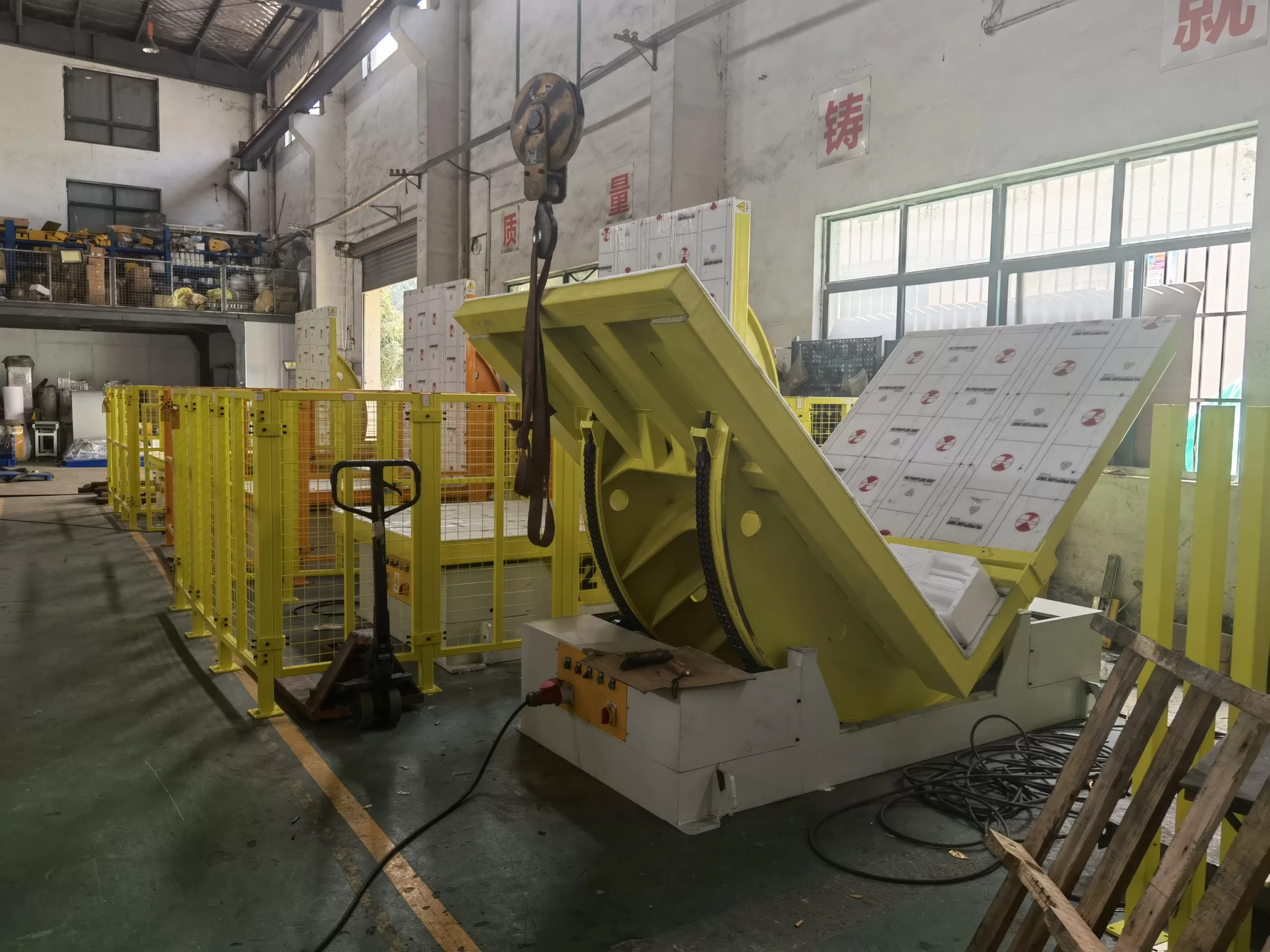
Are you struggling to understand the complex electrical wiring needed for your industrial mold upender? Improper wiring can lead to equipment malfunction, safety hazards, and costly downtime. Discover the essential electrical requirements to keep your mold upender running smoothly and safely!
The electrical wiring for industrial mold upenders must adhere to stringent safety standards and regulations. This includes proper grounding, appropriate wire gauges, correct voltage and current ratings, and the use of suitable enclosures and disconnecting means. Compliance with these requirements ensures safe and efficient operation, preventing electrical hazards and equipment damage.
Understanding the electrical wiring requirements for industrial mold upenders can be daunting, but it's crucial for ensuring safety and efficiency. Let's delve deeper into the specific guidelines and best practices you need to know.
Electrical Safety Standards for Mold Upenders
The first step in powering your mold upender is understanding the relevant electrical safety standards. These standards are designed to protect personnel and equipment from electrical hazards.
What electrical safety standards apply to industrial mold upenders? Key standards include OSHA regulations (29 CFR 1910 Subpart S - Electrical), NFPA 79 (Electrical Standard for Industrial Machinery), and the National Electrical Code (NEC). Compliance with these standards is essential for a safe and code-compliant installation.

Navigating Key Electrical Standards
Understanding the roles of OSHA, NFPA 79, and the NEC is crucial:
- OSHA (Occupational Safety and Health Administration): OSHA regulations are mandatory legal requirements for workplace safety. They reference and often incorporate other standards like the NEC and NFPA 79.
- NFPA 79 (Electrical Standard for Industrial Machinery): This standard focuses specifically on the electrical equipment within industrial machinery, including mold upenders. It provides detailed requirements for wiring, components, and protection methods.
- NEC (National Electrical Code): While NFPA 79 addresses the internal wiring of the machine, the NEC primarily covers the building's electrical system and the connection to the machine.
Deeper Dive: Understanding Component Requirements According to UL 508A
UL 508A, Standard for Industrial Control Panels, provides detailed requirements for components used in industrial control panels, which are often an integral part of mold upenders. Understanding how to select and use components that comply with UL 508A is crucial for ensuring the safety and reliability of your equipment.
Key Considerations for UL 508A Compliance
-
Listed vs. Recognized Components:
- Listed Components: These devices have been fully evaluated and certified by a Nationally Recognized Testing Laboratory (NRTL) like UL for a specific purpose. If a listed device is provided in an industrial control panel and specific component requirements are not described in the UL 508A Standard, it is generally acceptable for use.
- Recognized Components: These are components that have been evaluated for use within a larger piece of equipment. They have not been fully tested for stand-alone applications and must be used according to specific conditions outlined in the manufacturer’s “Procedure” (a document detailing the component’s limitations and proper application).
-
Component Selection Table:
- UL 508A includes a detailed table (formerly Supplement SA, now a standalone document) that specifies requirements for various components used in industrial control panels. This table includes references to UL standards, category control numbers, and notes on specific usage conditions.
-
Enclosure-Mounted Components:
- For components mounted on the enclosure of the industrial control panel, ensure they have appropriate Type ratings (e.g., Type 1, Type 4X) as per UL 50 or UL 50E, depending on the environmental conditions of the intended use.
-
Wiring and Connections:
- Use Listed or Recognized wire connectors and terminal blocks suitable for the conductor size and material, complying with UL 486A/B and UL 1059 standards, respectively.
Polymeric (Plastic) Mechanical Parts:
- Supporting Live Parts: Any plastic part that physically supports live parts, such as standoffs for bus bars, must comply with UL 508A, Section 13, Insulating Materials.
- Providing Insulation: If the plastic part provides insulation of live parts in lieu of electrical spacings, it must comply with Section 12, Insulating Barriers, or 29.2.3.
- Mechanical Intrusion Barrier: Parts that serve only as a mechanical intrusion barrier are not required to be Listed, Recognized, or described in a Procedure.
Examples of Component Requirements from UL 508A:
| Component Description | UL Standard | Category Control Number(s) | Notes |
|---|---|---|---|
| Grounding/Bonding Braid | UL 467 | KDER | Sized according to Section 15.1 |
| Terminal Blocks | UL 1059 | XCFR2 | Suitable for field connection for the conductor size required by 15.1 |
| Pressure Wire Connectors | UL 486A, UL 486B | ZMVV | Suitable for the conductor size required by 15.1 |
| Industrial Control Panel Enclosure | UL 508A | NITW | |
| Cable Assemblies and Fittings | UL 2238 | CYJV, CYJV2 | Recognized assemblies and fittings suitable for field wiring must be marked or identified for this application. All other applications must be Procedure described. |
| Fuses | UL 248 Series | JDDZ | Must comply with applicable spacing requirements in 10.8 |
| Surge Protective Devices | UL 1449 | VZCA, VZCA2 | SPDs that are outside the guidelines of Table 2 must be procedure described. |
Practical Implications
- Initial Design: Carefully review the UL 508A component selection table during the initial design phase to ensure all components meet the necessary requirements.
- Documentation: Maintain detailed records of all components used, including their UL listing or recognition status, category control numbers, and any applicable Procedures.
- Training: Ensure that personnel involved in the construction and maintenance of industrial control panels are trained on UL 508A requirements and component selection.
- Regular Updates: Stay informed about updates to UL 508A and related documents, as requirements can change over time.
By understanding and adhering to the component requirements outlined in UL 508A, you can significantly improve the safety and reliability of your industrial control panels and, by extension, the mold upenders they control.
Industrial Wiring Best Practices
Beyond adhering to safety standards, following best practices for industrial wiring is critical for ensuring the long-term reliability and performance of your mold upender.
What are the essential industrial wiring best practices for mold upenders? This includes using the correct wire gauge for the load, proper conduit and cable management, secure connections, and clear labeling. These practices minimize the risk of electrical faults, overheating, and premature equipment failure.
Implementing Proper Wiring Techniques
- Wire Gauge Selection: Choosing the correct wire gauge is essential to prevent overheating and voltage drop. Use the appropriate gauge based on the ampacity requirements of the mold upender's motor and other electrical components.
- Conduit and Cable Management: Employing proper conduit and cable management techniques protects wires from physical damage, moisture, and other environmental factors. Securely fasten conduits and cables to prevent movement and strain on connections.
- Secure Connections: Use high-quality connectors and terminals to ensure secure and reliable connections. Properly torque all connections to prevent loosening over time, which can lead to arcing and overheating.
- Clear Labeling: Clearly label all wires and components to facilitate troubleshooting and maintenance. Use durable labels that can withstand the industrial environment.
- Grounding: A proper grounding system is critical for safety. Ground all non-current-carrying metal parts of the mold upender to provide a path for fault currents.
- Regular Inspections: Conduct regular inspections of the electrical wiring and connections. Look for signs of damage, wear, or corrosion, and address any issues promptly.
- Surge Protection: Install surge protection devices to protect sensitive electronic components from voltage spikes and surges.
By implementing these best practices, you can minimize the risk of electrical problems and ensure the reliable operation of your mold upender.
Advanced Wiring Protection
- Use cable trays to manage and protect wiring runs, ensuring cables are not exposed to physical damage or excessive bending.
- Apply heat shrink tubing to exposed connections for added insulation and protection against moisture.
- Use liquid-tight connectors in wet or damp environments to prevent water from entering electrical enclosures.
By paying attention to these details, you can create a safer and more reliable electrical system for your mold upender.
Power Supply and Installation Guidelines
Selecting the right power supply and following proper installation guidelines are essential for the safe and efficient operation of your mold upender.
What power supply considerations are important for industrial mold upenders? Ensure the power supply meets the voltage, current, and frequency requirements of the upender. Follow installation guidelines, including proper disconnects, overload protection, and adherence to local electrical codes, for a safe and reliable setup.
Ensuring Proper Power Delivery
- Voltage and Current Requirements: Verify that the power supply voltage and current ratings match the specifications of the mold upender's motor and control system.
- Disconnecting Means: Install a readily accessible disconnecting means (e.g., a circuit breaker or fused disconnect switch) near the mold upender. This allows for safe isolation of the equipment during maintenance or emergencies.
- Overload Protection: Provide overload protection for the motor using appropriately sized overload relays or circuit breakers. This protects the motor from damage due to excessive current draw.
- Ground Fault Protection: Implement ground fault protection to detect and interrupt ground faults, minimizing the risk of electrical shock.
Advanced Installation Tips for Mold Upenders
Choosing the right Disconnect
-
Selecting Disconnect Type:
- Molded Case Circuit Breaker: Offers overcurrent protection and disconnecting means in one device. Suitable for branch circuit protection.
- Enclosed Switch: Provides a reliable disconnecting means. Can be fused for overcurrent protection.
- Manual Motor Controller: Suitable as a motor disconnect if marked "Suitable as motor disconnect."
-
Component Listing:
- Listed Components: Use components that are Listed under UL standards such as UL 489 for molded case circuit breakers, UL 98 for enclosed switches, and UL 508 for manual motor controllers.
- Recognized Components: Recognized components can be used within their electrical ratings. Ensure the component and its environmental rating are specifically included in the manufacturer's Procedure.
-
Location and Accessibility:
- The disconnecting means shall be readily accessible and located within sight of the controller location, as per NEC requirements. If out of sight, the controller should be marked with a warning label indicating the location and identification of the disconnecting means.
Wiring Methods
-
General Requirements:
- Wiring methods should comply with NEC Article 300, ensuring that wiring is protected from physical damage and environmental conditions.
- Use appropriate wiring types such as THHN/THWN conductors within conduit, or flexible cords and cables approved for the conditions of use.
-
Raceways and Cable Trays:
- Metal Raceways: Use metal raceways such as EMT (Electrical Metallic Tubing), IMC (Intermediate Metal Conduit), or rigid metal conduit for physical protection and grounding continuity.
- Cable Trays: Cable trays can be used for supporting and routing multiple cables, provided they are installed in accordance with NEC Article 392. Ensure that only approved wiring methods are installed in cable tray systems.
-
Conductor Requirements:
- All conductors should be insulated unless otherwise permitted. The insulation type should be approved for the voltage, operating temperature, and location of use.
- Insulated conductors shall be distinguishable by appropriate color or other suitable means as being grounded conductors, ungrounded conductors, or equipment grounding conductors.
-
Flexible Cords and Cables:
- Flexible cords and cables can be used for specific applications such as pendants, wiring of fixtures, and connection of portable equipment.
- They must be approved for conditions of use and location. Ensure that flexible cords are protected from accidental damage and supported to prevent physical strain.
Electrical Wiring Considerations:
-
Enclosures:
- Use enclosures that are appropriate for the environmental conditions. In damp or wet locations, enclosures should prevent moisture or water from entering and accumulating within.
- Cabinets, cutout boxes, fittings, boxes, and panelboard enclosures should be mounted with at least a 0.25-inch airspace between the enclosure and the supporting surface.
-
Grounding and Bonding:
- Ensure that metal raceways, cable trays, cable armor, cable sheath, enclosures, frames, fittings, and other metal noncurrent-carrying parts are effectively bonded to ensure electrical continuity and the capacity to conduct safely any fault current.
- Any nonconductive paint, enamel, or similar coating should be removed at threads, contact points, and contact surfaces or be connected by means of fittings designed to make such removal unnecessary.
Portable Cables:
-
Conductor Construction:
- Multiconductor portable cable for use in supplying power to portable or mobile equipment at over 600 volts, nominal, should consist of No. 8 or larger conductors employing flexible stranding.
-
Shielding:
- Cables operated at over 2,000 volts should be shielded for the purpose of confining the voltage stresses to the insulation.
-
Grounding Conductors:
- Grounding conductors should be provided and all shields should be grounded.
-
Fittings and Terminations:
- Connectors used to connect lengths of cable in a run should be of a type that lock firmly together. Provisions should be made to prevent opening or closing these connectors while energized. Strain relief should be provided at connections and terminations.
By carefully considering these electrical wiring requirements and implementing best practices, you can ensure the safe, reliable, and efficient operation of your mold upender system. Compliance with relevant standards and attention to detail in installation and maintenance will minimize downtime and protect personnel and equipment from electrical hazards.
Troubleshooting Common Electrical Issues
Even with proper installation, electrical issues can arise. Knowing how to troubleshoot common problems is essential for minimizing downtime.
What are the common electrical issues with mold upenders and how can they be resolved? These include motor failures, control system malfunctions, wiring faults, and power supply problems. Troubleshooting involves systematic inspection, testing, and repair or replacement of faulty components to restore the upender to proper operation.
Here's a breakdown of some troubleshooting points:
Identifying and Resolving Electrical Problems
- Motor Failures: Check for tripped overload relays, shorted windings, or damaged bearings. Replace the motor or repair as needed.
- Control System Malfunctions: Inspect control system components (e.g., PLCs, relays, sensors) for proper operation. Use a multimeter to test for voltage and continuity. Replace any faulty components.
- Wiring Faults: Look for loose connections, damaged insulation, or corroded terminals. Tighten connections, repair or replace damaged wiring, and clean corroded terminals.
- Power Supply Problems: Verify that the power supply is delivering the correct voltage and current. Check for blown fuses or tripped circuit breakers. Replace the power supply if necessary.
- Ground Faults: Use a ground fault locator to identify and isolate ground faults. Repair or replace any faulty wiring or components that are causing the ground fault.
- Emergency Stop Issues: Inspect the emergency stop circuit for proper operation. Ensure that all emergency stop buttons are functioning correctly and that the circuit is not compromised.
By following these troubleshooting steps, you can quickly identify and resolve common electrical issues, minimizing downtime and keeping your mold upender running smoothly.
Conclusion
Ensuring the safe and efficient operation of your industrial mold upender hinges on understanding and adhering to stringent electrical requirements. This comprehensive guide has provided an in-depth look at the key standards, best practices, and troubleshooting techniques necessary for powering your upender reliably. From OSHA regulations and NFPA 79 to UL 508A and advanced installation tips, each element plays a critical role in minimizing downtime and protecting personnel. By implementing these guidelines, you'll optimize the performance and longevity of your mold upender.