Efficient Mold Clamping with FW-S Series
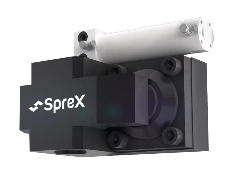
The FW-S Series Hydraulic Clamping System provides a robust and reliable solution for mold clamping applications requiring an upward or downward clamping direction. This system is engineered to enhance both the speed and safety of mold changes in manufacturing environments.
Equipped with an automatic movable cylinder, the FW-S clamps facilitate the process of securing the mold. The integrated design allows for automatic clamping action after a simple manual positioning, contributing to a safer operational workflow.
Applications
This hydraulic clamping system is versatile and widely adopted across various mold processing industries. It is a crucial component for:
- Plastic Injection Molds
- Stamping Dies
- Die Casting Molds
- Glass Molds
- Rubber Molds
- Metallurgy Molds
It is particularly indispensable for optimizing operations in injection molding and die casting manufacturing.
Technical Specifications
The FW-S Series is available in several models, each offering different clamping forces and strokes to suit diverse equipment needs. Key technical parameters are detailed in the table below:
| Model | Clamping Force (kN at 25MPa) | Max. Stroke (mm) | Driving Air Pressure (MPa) | Clamp Speed (mm/s) | Approx. Weight (kg) |
|---|---|---|---|---|---|
| FW2-S | 20 | 150 | 0.4-0.55 | 30-80 (Adjustable) | 2 |
| FW4-S | 40 | 150 | 0.4-0.55 | 30-80 (Adjustable) | 4.8 |
| FW6-S | 60 | 200 | 0.4-0.55 | 30-80 (Adjustable) | 7.2 |
| FW10-S | 100 | 300 | 0.4-0.55 | 30-80 (Adjustable) | 13 |
| FW16-S | 160 | 300 | 0.4-0.55 | 30-80 (Adjustable) | 23 |
| FW25-S | 250 | 300 | 0.4-0.55 | 30-80 (Adjustable) | 36 |
| FW50-S | 500 | 300 | 0.4-0.55 | 30-80 (Adjustable) | 80 |
Features and Benefits
The design of the FW-S series focuses on precision, ease of use, and safety:
- Precise Control: Features an advanced electrical system controller, often incorporating a programmable controller for accurate operation and a user-friendly interface.
- Enhanced Safety: Incorporates multiple layers of safety protection mechanisms, significantly reducing risks and ensuring the safety of operators during the mold clamping and unclamping processes.
- Automated Movement: The automatic movable cylinder simplifies the clamping sequence.
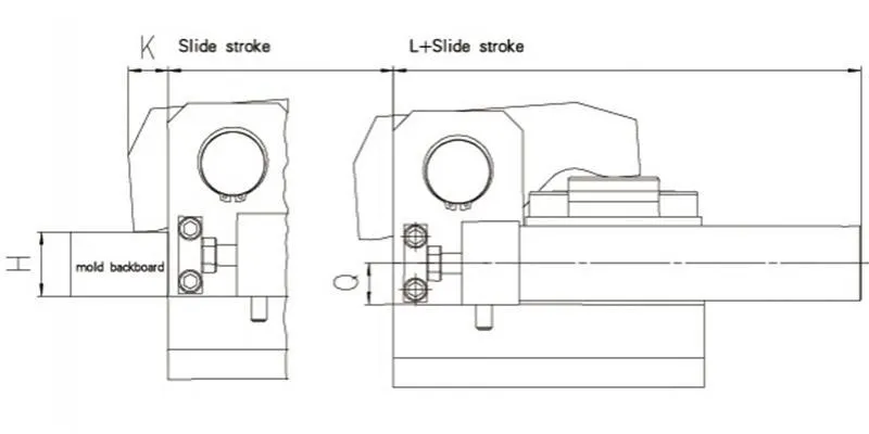
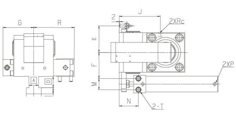
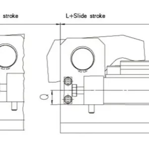
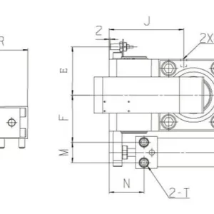
Dimensions
Detailed dimensions for each model are critical for integration. The following table provides key measurements, corresponding to the dimension diagrams.
| Model | A | B | C | D | E | F | G | H | I | J | K | L | M | N | O |
|---|---|---|---|---|---|---|---|---|---|---|---|---|---|---|---|
| FW2 | 60 | 65 | 58 | 46.5 | 39.5 | 18 | 1/4 | 48 | M5X35 | 1/8 | 15 | 18 | 108.5 | 25 | |
| FW4 | 66 | 72 | 80 | 54 | 47 | 18 | 1/4 | 70 | M5X35 | 1/8 | 15 | 23 | 108.5 | 30 | |
| FW6 | 80 | 92 | 85 | 66 | 58 | 24 | 1/4 | 76 | M8X45 | 1/8 | 21 | 30 | 119 | 30 | |
| FW10 | 90 | 110 | 109 | 75 | 66 | 32 | 1/4 | 95 | M10X55 | 1/8 | 26 | 30 | 137 | 40 | |
| FW16 | 100 | 119 | 125 | 84 | 75 | 32 | 1/4 | 120 | M10X55 | 1/8 | 26 | 30 | 137 | 50 | |
| FW25 | 113 | 150 | 150 | 97.5 | 95.5 | 41 | 1/4 | 135 | M12X70 | 1/4 | 32 | 30 | 163 | 50 | |
| FW50 | 155 | 200 | 200 | 140 | 135 | 110 | 1/4 | 160 | M16X85 | 1/4 | 38 | 30 | 172 | 60 |
Note: 'H' in the table indicates the standard thickness of mold base plates compatible with the clamps. Custom sizes are available.


Reviews
There are no reviews yet.