

Is your mold upender underperforming after installation? Don't let improper setup compromise your investment. A thorough post-installation checklist is crucial for verifying functionality, ensuring safety, and maximizing the lifespan of your equipment. This proactive approach helps identify and rectify potential issues before they escalate into costly problems.
After installing a mold upender, the checklist ensures optimal performance by verifying proper setup, safety mechanisms, and functionality. Regular checks, adjustments, and adherence to the checklist guarantee long-term reliability and prevent potential issues, maximizing efficiency and minimizing downtime. This guarantees operational readiness and longevity.
Investing in a mold upender is a significant step towards enhancing your manufacturing capabilities. However, the benefits can only be fully realized with meticulous post-installation procedures. Let's delve into a comprehensive checklist to help you ensure your mold upender operates at peak performance.

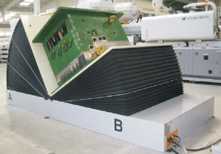
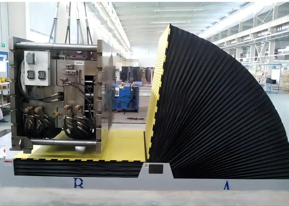
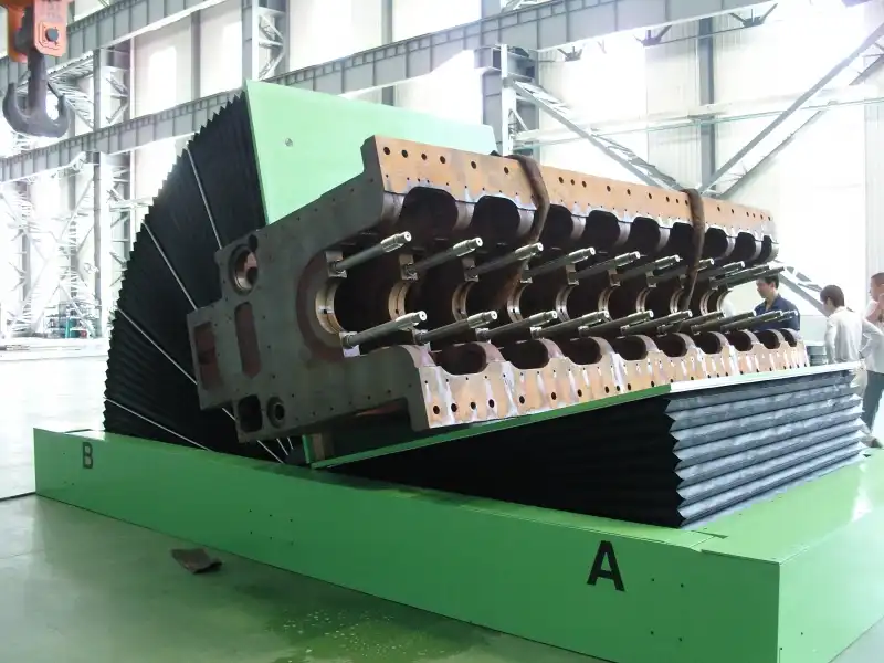
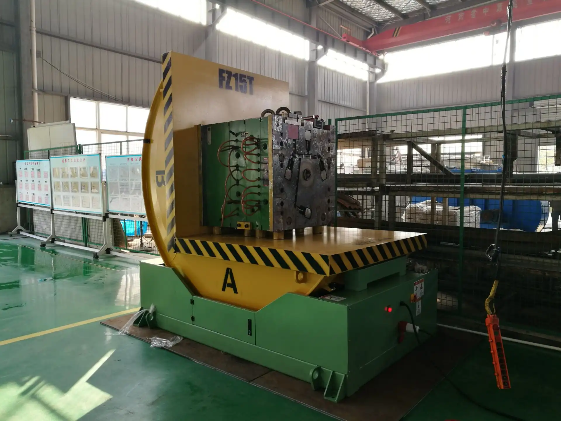
Verifying Mechanical and Structural Integrity
What are the key mechanical checks to guarantee your mold upender's structural integrity? A meticulous inspection is paramount. Verifying the mechanical and structural integrity of your mold upender post-installation involves scrutinizing all bolted connections, welds, and moving parts to ensure they meet specifications. This includes confirming the stability of the base, smooth operation of the tilting mechanism, and proper alignment of all components.
Post-installation mechanical checks involve examining bolted connections for tightness, inspecting welds for integrity, and ensuring smooth operation of moving parts. Verifying the base stability and alignment are critical for ensuring structural integrity and preventing future mechanical failures.
Detailed Inspection Points
To ensure a comprehensive assessment, consider the following inspection points:
- Base Stability: Verify that the upender is securely anchored to the floor. Check for any signs of instability or rocking during operation.
- Bolted Connections: Inspect all bolts for proper torque. Use a calibrated torque wrench to confirm they meet the manufacturer's specifications.
- Welds: Examine all welds for cracks, porosity, or other defects. Perform non-destructive testing (NDT) if necessary.
- Moving Parts: Ensure smooth and unrestricted movement of all components. Lubricate as needed.
- Alignment: Check the alignment of the tilting mechanism and mold supports. Misalignment can lead to uneven loading and premature wear.
Addressing Potential Issues
If any issues are identified during the inspection, take immediate corrective action:
- Loose Bolts: Tighten bolts to the specified torque. Replace any damaged or corroded bolts.
- Weld Defects: Repair or re-weld any defective welds. Ensure that the repairs are performed by a qualified welder.
- Restricted Movement: Investigate the cause of any restricted movement. Lubricate, adjust, or replace components as needed.
- Misalignment: Adjust the alignment of the tilting mechanism and mold supports. Use shims or other methods to achieve proper alignment.
Ensuring Longevity through Preventative Measures
Beyond addressing immediate issues, proactive measures can extend the lifespan of your mold upender:
- Regular Lubrication: Establish a lubrication schedule to keep moving parts functioning smoothly.
- Periodic Inspections: Conduct regular inspections to identify and address potential issues before they escalate.
- Load Capacity Awareness: Adhere to the specified load capacity. Overloading can cause structural damage and mechanical failure.
- Protective Coatings: Apply protective coatings to prevent corrosion and wear.
Weight Capacity Considerations
Understanding the weight capacity of your mold upender is critical for safe and efficient operation. Exceeding the specified load limits can result in severe mechanical stress, equipment damage, and potential safety hazards. The weight capacity refers to the maximum load the upender can safely handle during tilting and rotation.
To illustrate the significance of weight considerations, consider the following data:
| Mold Size | Approximate Weight (Tons) | Recommended Upender Capacity (Tons) | Safety Factor |
|---|---|---|---|
| Small | 5 | 10 | 2.0 |
| Medium | 15 | 25 | 1.67 |
| Large | 30 | 50 | 1.67 |
| Extra Large | 50 | 80 | 1.60 |
The safety factor is calculated as the ratio of the upender's capacity to the mold's weight. A higher safety factor provides a greater margin of safety and reduces the risk of overloading.
Addressing Welding Concerns
Welding is an essential part of the upender's construction, and the quality of welds directly impacts the upender's structural integrity. Potential issues include porosity, cracks, incomplete fusion, and slag inclusions. These defects can weaken the weld joint, making it susceptible to failure under stress.
Ensuring Safety Protocols
- Certification: Ensure all welders are certified according to AWS standards.
- Material Compatibility: Use welding electrodes compatible with the base materials.
- Inspection: Inspect welds for defects using visual and non-destructive testing (NDT) methods.
- Repair: Repair defective welds using qualified personnel.
By prioritizing these measures, you can ensure that welding issues do not compromise the reliability and longevity of your mold upender.
By meticulously inspecting and addressing mechanical and structural concerns, you'll ensure your mold upender operates safely and reliably for years to come.


Evaluating Hydraulic and Electrical Systems
How do you confirm the reliability of hydraulic and electrical systems? Assessing these systems is critical. Evaluating the hydraulic and electrical systems of a mold upender requires a meticulous approach, starting with confirming all wiring connections are secure and properly insulated. Inspect hydraulic lines for leaks, kinks, or damage, and verify pressure gauges are accurate. Additionally, confirm that safety interlocks function correctly.
Verifying secure wiring connections, inspecting hydraulic lines for leaks, and validating the accuracy of pressure gauges are essential. Also, confirming the functionality of safety interlocks ensures that the hydraulic and electrical systems are reliable.
Key Inspection Areas
Focus on these crucial areas during your evaluation:
- Wiring Connections: Verify that all wiring connections are secure, properly insulated, and free from corrosion.
- Hydraulic Lines: Inspect hydraulic lines for leaks, kinks, or damage. Ensure that fittings are tight.
- Pressure Gauges: Verify the accuracy of pressure gauges. Calibrate or replace if necessary.
- Safety Interlocks: Confirm that all safety interlocks function correctly. These should prevent operation if safety guards are not in place or if other safety conditions are not met.
- Motor Performance: Assess the performance of electric motors, checking for unusual noises, overheating, or vibration.
Diagnosing and Resolving Common Issues
Addressing common hydraulic and electrical problems promptly is essential:
- Leaks: Repair any hydraulic leaks immediately. Replace damaged hoses or fittings.
- Loose Connections: Tighten any loose wiring connections. Replace damaged or corroded connectors.
- Faulty Gauges: Replace faulty pressure gauges with calibrated units.
- Interlock Malfunctions: Troubleshoot and repair any safety interlock malfunctions.
- Motor Problems: Investigate and resolve any motor performance issues. This may involve lubrication, repair, or replacement.
Preventive Maintenance Strategies
Implementing preventive maintenance will help to avoid future problems:
- Scheduled Inspections: Perform scheduled inspections of hydraulic and electrical systems.
- Oil Analysis: Conduct regular oil analysis to monitor the condition of hydraulic fluid.
- Filter Replacement: Replace hydraulic filters according to the manufacturer's recommendations.
- Component Replacement: Replace worn or aging components proactively.
Electrical Component Ratings
Confirming the electrical component ratings is paramount for operational safety and preventing electrical failures. Overloading components can lead to overheating, insulation breakdown, and potentially hazardous situations. All electrical components, including motors, transformers, and circuit breakers, have specific voltage, current, and power ratings that should not be exceeded.
Consider this table that explains the relationship between voltage, current, and power:
| Component | Voltage Rating (V) | Current Rating (A) | Power Rating (kW) | Safety Margin (%) |
|---|---|---|---|---|
| Motor | 480 | 20 | 15 | 20 |
| Transformer | 480 | 30 | 20 | 15 |
| Circuit Breaker | 480 | 25 | N/A | 10 |
Each component is listed with its voltage, current, and power ratings, along with a safety margin expressed as a percentage.
Proper Hydraulic Fluid Selection
Proper hydraulic fluid selection is essential for maintaining the efficiency, reliability, and longevity of the mold upender's hydraulic system. Selecting the wrong fluid can lead to a variety of problems, including reduced performance, increased wear, corrosion, and premature component failure.
Different types of hydraulic fluids are available, each with its own unique properties and advantages. The most common types include mineral-based oils, synthetic fluids, water-glycol fluids, and phosphate ester fluids.
Verifying Interlock Functionality
Verifying the proper functionality of safety interlocks is a critical step in ensuring the safe operation of the mold upender. Safety interlocks are designed to prevent the machine from operating under unsafe conditions, such as when safety guards are not in place or when critical parameters are exceeded.
By meticulously evaluating and maintaining the hydraulic and electrical systems, you can ensure the safe, reliable, and efficient operation of your mold upender.

Calibrating Sensors and Control Systems
Why is sensor calibration crucial? Accurate measurements are key. Calibrating sensors and control systems is pivotal for ensuring precise and reliable operation of your mold upender. Accurate sensor readings are essential for maintaining consistent performance, preventing errors, and safeguarding both the equipment and personnel.
Sensor calibration ensures accurate readings, which are vital for consistent performance and safety. Regularly calibrating pressure sensors, proximity switches, and temperature sensors, and validating the control system's responsiveness are all necessary to maximize efficiency.
Calibration Procedures
Follow these calibration procedures for optimal results:
- Pressure Sensors: Use a calibrated pressure gauge to verify the accuracy of pressure sensors. Adjust the sensor output as needed.
- Proximity Switches: Check the activation distance of proximity switches. Adjust the switch position as needed to ensure proper activation.
- Temperature Sensors: Use a calibrated thermometer to verify the accuracy of temperature sensors. Adjust the sensor output as needed.
- Load Cells: Calibrate load cells using certified test weights. Verify the accuracy of the weight readings across the full operating range.
Validating Control System Responsiveness
Test the control system's response to various inputs and conditions:
- Manual Controls: Verify that manual controls operate smoothly and accurately.
- Automatic Controls: Test the automatic control functions, such as tilting and rotation. Ensure that these functions respond correctly to sensor inputs.
- Emergency Stop: Confirm that the emergency stop function halts all operations immediately.
Troubleshooting Calibration Issues
If any calibration issues arise, address them promptly:
- Sensor Drift: Recalibrate sensors that exhibit drift or inaccurate readings.
- Control System Errors: Troubleshoot any errors in the control system logic.
- Component Failure: Replace any faulty sensors or control system components.
Implementing A Data-Driven Approach
To optimize the performance of the upender, consider implementing a data-driven approach to sensor management and calibration. This involves collecting and analyzing data related to sensor performance, such as calibration drift, error rates, and failure frequency. By analyzing these data, you can identify trends, predict potential issues, and optimize the calibration schedule to ensure that the sensors are always operating within acceptable limits.
Regular Audits for Continual Improvements
Regularly scheduled audits are important for maintaining proper upender operations over the long term. This entails reviewing maintenance records, assessing sensor performance, and evaluating control system responsiveness, and checking safety protocols. The audits help uncover any areas needing improvement, ensuring adherence to established procedures and identifying potential areas for optimization. By implementing suggested upgrades, the process helps sustain a safe and efficient working environment.
By carefully calibrating sensors and control systems, you can optimize the performance, safety, and reliability of your mold upender.

Establishing Standard Operating Procedures (SOPs)
What are the benefits of SOPs? Consistency and safety. Establishing Standard Operating Procedures (SOPs) for your mold upender ensures consistent and safe operation. Well-defined SOPs provide clear guidelines for operators, maintenance personnel, and other stakeholders, promoting efficiency and reducing the risk of accidents.
SOPs ensure consistent and safe operation by providing guidelines for operators and maintenance personnel. This minimizes errors, maximizes efficiency, and reduces the risk of accidents. Properly documented procedures are essential for maintaining optimal performance.
Follow these procedures to establish robust SOPs:
- Define Scope: Clearly define the scope of the SOPs. Specify which tasks and operations are covered.
- Identify Steps: Identify all steps involved in each task or operation.
- Document Procedures: Document each step in a clear and concise manner. Use diagrams and illustrations where appropriate.
- Incorporate Safety Precautions: Integrate safety precautions into each procedure. Highlight potential hazards and required safety equipment.
- Training: Provide comprehensive training to all personnel who will be using the SOPs.
- Review and Update: Review and update the SOPs regularly. Incorporate feedback from operators and maintenance personnel.

Thorough post-installation procedures, including mechanical and electrical verification, sensor calibration, and SOP development, are crucial for ensuring the safe, reliable, and efficient operation of your mold upender. Diligent adherence to these steps will maximize your investment and provide years of dependable service. SOP’s, in particular, ensure a mold upender runs safely and is in accordance with company standards. These safety SOP’s can prevent workers’ comp claims as well as reduce costly workplace accidents.
Conclusion
Implementing a thorough post-installation checklist is paramount for ensuring the optimal performance and longevity of your mold upender. By diligently verifying mechanical and structural integrity, evaluating hydraulic and electrical systems, calibrating sensors, and establishing SOPs, you can maximize efficiency, minimize downtime, and prioritize safety. Prioritizing [Installation testing]() guarantees a reliable and productive operation.